 English

Views: 0 Author: Site Editor Publish Time: 2026-11-11 Origin: Site
Mid-harvest downtime drains profitability at an alarming rate. When crop conditions reach their peak, catastrophic drivetrain failures cascade into massive financial losses. Combine harvester gearboxes and tension pulleys endure extreme torque. They operate continuously in heavy vibration and high-particulate environments. Relying on reactive maintenance guarantees sheared shafts, destroyed belts, and multi-day repair delays. We must shift our focus immediately. Move away from basic visual inspections. Implement predictive maintenance frameworks. Evaluate wear patterns technically. Strategically procure replacement components to guarantee fleet reliability and keep machines in the field where they belong. A proactive approach prevents minor component fatigue from escalating into complete system failure during the tightest harvest windows.
Fluid and Thermal Baselines: Routine fluid analysis and thermal monitoring of the combine harvester gearbox are critical for detecting premature bearing and gear face wear before catastrophic failure.
Alignment is Non-Negotiable: A failing or misaligned harvester tension pulley directly transfers destructive lateral loads to gearbox input shafts and belts.
Strategic Sourcing: Standardizing replacement components using verified suppliers (e.g., FM WORLD harvester parts) reduces compatibility risks and standardizes maintenance intervals across mixed fleets.
Pre-Season vs. In-Season: Differentiate between deep-teardown preventative maintenance (pre-season) and rapid, non-invasive diagnostic checks (in-season).
Defining success in agricultural fleet management requires strict operational criteria. A successful maintenance program achieves zero unplanned drivetrain downtime during the harvest window. It maximizes the lifespan of expensive wear parts. Equipment operators must understand the mechanics of cascading failures. A single point of failure rarely remains isolated. A seized tensioner bearing creates an immediate chain reaction. The friction destroys heavy-duty drive belts within minutes. The resulting heat transfers to adjacent components rapidly. This thermal event often compromises the main rotor or chopper gearbox, turning a minor bearing replacement into a major overhaul.
Compare the labor and parts cost of pre-season preventative replacement against emergency repair costs. The math heavily favors proactive intervention. In-field breakdowns require emergency parts shipping. They demand field service technician dispatch. Most importantly, they cause severe crop yield loss due to harvest delays. Weather windows remain unforgiving. Replacing a suspect pulley or gearbox seal in the shop costs a fraction of the downtime incurred when a machine dies in the field. Preventative replacement acts as an insurance policy for your harvest yield.
Initial Component Failure | Immediate Mechanical Effect | Cascading System Damage | Estimated Repair Delay |
|---|---|---|---|
Seized Tensioner Bearing | Belt friction and extreme heat generation | Drive belt snaps, wraps around adjacent shafts | 4 to 6 hours |
Worn Gearbox Input Seal | Slow gear oil leak into the field | Internal bearings overheat, gear teeth shear off | 2 to 3 days |
Misaligned Drive Pulley | Uneven belt wear and lateral shaft loading | Input shaft bends, destroying internal gearbox races | 1 to 2 days |
Blocked Breather Valve | Internal casing pressure builds up | Multiple seals blow out simultaneously | 5 to 8 hours |
The table above illustrates how rapidly a minor oversight escalates. You cannot afford to wait for a component to fail completely. Implementing a structured inspection routine catches these initial failures before they progress to the cascading damage phase. This approach keeps your combine moving and your operators productive.
Gear oil serves as the lifeblood of your drivetrain. You must regularly check gear oil for thermal breakdown and viscosity loss. Look closely for moisture ingress. Water contamination presents as a distinct milky appearance in the fluid. Particulate contamination destroys hardened gear faces. Use magnetic drain plugs to capture ferrous metal shavings. Laboratory fluid analysis takes this a step further. Lab reports identify specific wear metals in parts per million. High brass levels indicate synchronizer or internal bushing wear. Elevated steel levels point directly to gear face pitting or bearing degradation. Catching these markers early prevents catastrophic lockups.
Strict OEM-aligned intervals for fluid changes are mandatory. You must adjust these intervals for severe operating conditions. High dust environments and extreme ambient temperatures degrade oil additives faster. Synchronize your Combine Harvester Gearbox oil changes with broader hydraulic and engine fluid replacement schedules. This synchronization reduces shop visits. It ensures all critical fluids maintain optimal protective properties. Always perform the initial break-in oil change strictly according to the manufacturer timeline to remove manufacturing debris.
Follow these exact steps when pulling a fluid sample for laboratory analysis:
Operate the combine for at least 30 minutes to bring the gear oil up to normal operating temperature and suspend particulates.
Clean the area around the drain plug thoroughly with brake parts cleaner to prevent external dirt from entering the sample bottle.
Open the drain plug and let a small amount of oil flow out to clear any debris resting directly on the magnetic plug.
Catch the mid-stream oil flow in a sterile sampling bottle, filling it to the indicated line.
Seal the bottle immediately, label it with the machine's serial number and current operating hours, and ship it to the lab.
Establishing baseline operating metrics prevents guesswork. Use infrared thermometers to map normal operating temperatures across the gearbox casing. Deploy vibration analysis tools to record baseline frequencies for the harvester gearbox under heavy load. You must know what a healthy system looks and sounds like. Interpret abnormal harmonic vibrations carefully. Localized hot spots near bearing caps indicate early bearing spalling. High-frequency vibrations often point to gear tooth pitting.
Isolating these harmonics requires technical precision. Combine harvesters generate massive background vibration. Rotors, sieves, and knife drives transfer harmonics through the chassis. You must isolate these vibrations from unbalanced adjacent systems to prevent misdiagnosis. Run the separator empty and selectively disengage drives where possible. This isolation confirms whether the vibration originates inside the gearbox or is transferring from a bent rotor shaft nearby. Document the temperature readings daily during the first week of harvest to establish a reliable baseline for the rest of the season.
Chaff and dust ingress threaten every rotating seal on the machine. Input and output shaft seals remain highly vulnerable to crop residue wrapping. Tough stalks wrap tightly around shafts, pushing past seal lips. Abrasive dust then enters the cavity, destroying the smooth seal surface. Post-harvest and daily cleaning protocols are absolutely necessary. You must remove crop residues daily. Clear guide-element buildup meticulously. This organic debris acts as a highly effective thermal blanket. It traps heat against the casing, causing the gearbox to overheat and bake the internal oil.
Never ignore breather valve functionality. Gearboxes generate heat, which expands the internal air. Breather valves allow this pressure to escape. Dust and oily residue frequently block these small vents. Blocked breather valves cause internal pressure buildup. This pressure seeks the path of least resistance. It leads directly to seal blowouts. A blown seal dumps gear oil into the field, leading to rapid internal component destruction. Check and clean breathers during every daily walk-around. Use a mild solvent and compressed air to ensure the breather cap rattles freely.
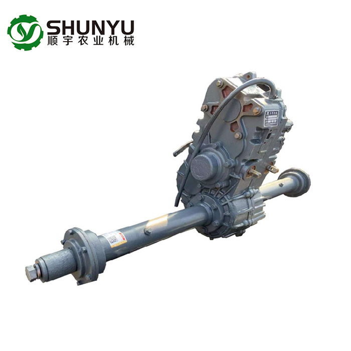
Tension release diagnostics form the core of pre-harvest inspections. You must release belt tension to properly evaluate the system. Manually spin the harvester tension pulley. Spin the chopper gearbox input shafts by hand. Check for rough spots in the rotation. Feel for drag or bearing play. You cannot detect these issues when the belt applies heavy side-load. The tension masks the internal friction. Releasing the belt reveals the true condition of the bearing races.
Measure radial and axial play accurately. Use dial indicators to quantify unacceptable play in the pulley bearings. Hand-feel only goes so far. A dial indicator provides hard data on bearing wear. Mount the magnetic base to a solid frame member and place the indicator tip against the pulley sheave. Push and pull the pulley to measure axial end-play. Alignment verification is equally critical. Compare straight-edge methods with modern laser alignment tools. Laser tools ensure the pulley remains perfectly coplanar with the drive and driven sheaves. Even slight angular misalignment causes the belt to ride hard against the pulley flange, generating massive heat and premature failure.
Outline the technical procedure for measuring belt deflection. Optimal spring tension keeps the belt seated without overloading the bearings. Use a mechanical deflection gauge or a sonic tension meter. Do not rely on the outdated rule-of-thumb press test. Inspect belts closely for visual degradation. Belts provide secondary symptoms of pulley failure. Edge fraying, sidewall glazing, or deep cracking indicate severe misalignment. They also point to seized tensioner bearings dragging against the belt back.
Understand the mechanical trade-offs of over-tensioning. More tension does not equal better performance. Over-tensioning eliminates belt slip but introduces catastrophic side-loads. This accelerated wear destroys both the pulley bearings and the adjacent gearbox shaft bearings. The shafts literally bend under the extreme lateral force. This bending fatigues the metal and crushes the roller bearings inside the gearbox casing. Always set tension strictly to OEM specifications.
Follow this procedure for setting proper belt tension:
Loosen the idler pulley locking nut completely to allow free movement of the tensioner arm.
Adjust the tensioning bolt until the belt feels snug, then attach your mechanical deflection gauge to the longest span of the belt.
Apply the manufacturer-specified force to the gauge and measure the deflection distance.
Tighten or loosen the tensioning bolt until the deflection distance matches the service manual specifications exactly.
Lock the idler nut, rotate the drive system by hand for three full revolutions to seat the belt, and re-check the deflection.
Evaluating replacement components requires a strict look at material specifications. Compare forged versus cast components carefully. Forged steel offers superior tensile strength. It provides necessary fatigue resistance in high-torque agricultural applications. Cast components often contain microscopic voids that lead to sudden shattering under shock loads. Your replacement strategy must prioritize metallurgy over initial purchase price. A cheap pulley that shatters in the field costs ten times more in lost harvesting time.
Evaluate bearing and seal quality rigorously. High-dust agricultural environments destroy standard bearings. Sealed-for-life bearings offer distinct advantages. Look for double-lip Nitrile or Viton seals. These materials resist heat and block microscopic dust particles effectively. Greasable bearings require strict, disciplined maintenance schedules. If your crew struggles with daily greasing protocols, sealed-for-life units provide better long-term reliability and prevent over-greasing blowouts.
Component Feature | Standard Aftermarket | High-Quality / OEM Equivalent |
|---|---|---|
Material Construction | Standard Cast Iron | Forged Steel or Ductile Iron |
Bearing Seals | Single-lip rubber | Double-lip Viton or Nitrile |
Machining Tolerance | +/- 0.05 inches | +/- 0.005 inches |
Lubrication Type | Standard lithium grease | High-temp polyurea synthetic |
Standardizing your fleet simplifies maintenance. Discuss the technical evaluation of FM WORLD harvester parts for fleet integration. Focus heavily on dimensional accuracy. Replacement parts must meet OEM-equivalent load ratings. Caliper measurements should confirm that shaft diameters and keyways match perfectly. Loose fits cause vibration. Tight fits require destructive force during installation. You want components that slide on cleanly and lock down securely without modification.
Analyze supply chain reliability. Partnering with suppliers that offer consistent availability changes your operational dynamic. It reduces the need for excessive on-farm parts hoarding. You free up capital while ensuring critical spares remain accessible. During the harvest window, parts availability dictates your uptime. Choose suppliers with proven logistics networks and deep inventory reserves for high-wear drivetrain components. Consistent part sourcing also means your mechanics learn the exact installation quirks of a specific brand, speeding up repair times.
Over-greasing represents one of the most common and destructive maintenance errors. High-pressure grease guns easily overpower bearing seals. Over-greasing blows out the delicate seal lips. Once the seal ruptures, it attracts field dust. The grease and dust mix to create a highly abrasive grinding compound. This compound circulates inside the bearing, destroying the polished races and ball bearings within days. Train operators on exact pump counts for every grease zerk. Wipe every zerk clean before attaching the gun to prevent pushing surface dirt directly into the bearing cavity.
Improper torque specs and fastener neglect cause structural failures. Highlight the risk of using pneumatic impact wrenches without torque sticks on critical mounting bolts. Over-torquing stretches the bolt past its yield point. Under-torquing allows brackets and fasteners to vibrate loose over time. This loosening leads to structural fatigue. It causes thread stripping in expensive cast housings. Always use calibrated torque wrenches for critical drivetrain installations. Mark torqued bolts with a paint pen to provide a quick visual reference for loosening during daily inspections.
Implement strict pre-harvest teardown checklists. Deep inspections require removing all drive belts to spin pulleys freely. Check gearbox backlash by rotating the input shaft while holding the output shaft stationary. Measure the play against factory tolerances. Replace worn, rusted, or stretched fasteners immediately. Do not reuse lock nuts on high-vibration brackets. This pre-season discipline prevents in-season disasters. Document every measurement in a fleet maintenance log to track wear trends over multiple seasons.
Establish standard operating procedures for daily in-season checks. Operators must perform daily blow-downs of the chopper gearbox area using compressed air. Visually check all casings for fresh oil weeping. Listen carefully for abnormal squeals or chirps upon separator engagement. Establish a mandatory checklist for keeping a rapid-response kit in the field. This in-field spares inventory must include spare belts, heavy-duty chains, and complete tensioner assemblies. Having these parts in the service truck minimizes downtime dramatically. A well-stocked field truck turns a half-day breakdown into a thirty-minute pit stop.
Audit your current fleet's maintenance logs immediately to identify overdue fluid changes and establish a baseline for the upcoming season.
Schedule immediate fluid sampling for all high-hour gearboxes to detect internal wear metals before catastrophic failure occurs.
Secure a pre-season inventory of critical belts, pulleys, and seals, keeping them stocked directly in your field service trucks.
Train your operators on proper daily blow-down procedures, exact grease volume limits, and visual inspection techniques for breather valves.
A: Change the oil after the first 50-hour break-in period to remove manufacturing debris. Afterward, replace the gear oil every 400 to 500 operating hours, or annually. In severe conditions with extreme dust or heat, shorten this interval to 300 hours. Always synchronize gearbox fluid changes with your broader hydraulic fluid schedules to ensure comprehensive drivetrain protection.
A: Early acoustic signs include high-pitched squealing or chirping during engagement. Visual signs include belt edge fraying, sidewall glazing, or cracking. Physical signs become apparent when tension is released; the pulley will exhibit excessive heat, rough rotation, or noticeable lateral drag when spun by hand.
A: Yes. A misaligned pulley transfers extreme lateral loads through the drive belt directly to the gearbox input shaft. This side-load bends the shaft microscopically, crushing the internal roller bearings and distorting the shaft seals. This leads to rapid oil loss and catastrophic internal gear failure.
A: Use an NLGI No. 2 lithium-complex grease or a high-quality polyurea grease. These formulations withstand high temperatures and heavy shock loads typical in agricultural applications. They also resist water washout and maintain their viscosity in extreme dust environments, protecting critical bearing races.
A: Do not rely on the manual thumb-press test. Use a mechanical deflection gauge to measure exact belt deflection per the manufacturer's specifications. For maximum accuracy, utilize a sonic tension meter that measures the vibration frequency of the belt span to confirm optimal spring tension.
A: Yes, they offer broad cross-compatibility. However, you must verify OEM part number matching before installation. Always check dimensional tolerances, shaft diameters, and load ratings with a caliper to ensure the replacement part perfectly matches the structural requirements of your specific combine model.


